Standard
Posted by
maftabmemonPosted on
January 6, 2015Posted under
UncategorizedComments
Leave a comment
Hello All,
I recently started learning Jun OS. The best way to learn is by practice, practise and practise.
In this post I will show how to set up JunOS on ESXI for labbing. In my other post I will provide with the different labs am doing on this topology.
Once you have ESXi 5.5 up and running download the junos-vsrx-12.1X46-D20.5-domestic.ova or firefly-perimeter-junos-vsrx-12.1X47-D10.4-domestic.ova.
Note that you will need to use your login to download. Juniper allows a user to create a new account and then you can download the firefly perimeter software.
In my setup I am deploying junos-vsrx-12.1X46-D20.5-domestic.ova.
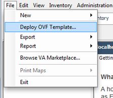
Once the download is complete you need to open your vSphere Client and connect to your ESXi server. Once connected select the Deploy OVF Template option from the file menu.
Select the source of the OVA file you downloaded from your local machine.

The next screen should be similar to the one below after the source has been selected.


Read and accept the end user license

The next screen will display the name for the virtual machine. You can change this if you would like

I am providing the name as Jun-OS-1 as I will be deploying 8 of these and 2 Cisco CSR 1000v for labbing.
Now you need to select the datastore

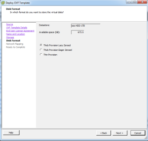
Next you will be offered the select the disk format. The default option of Thick Provision Lazy Zeroed is fine but for better performance you can select Thick Provision Eager Zeroed. To read more on the options go here.
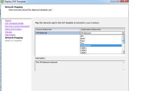
The next screen will ask you for the mappings for the Gigabit Ethernet interfaces that are defined in the OVF file. Just select the default here for now and we’ll come back to them after our machine is installed as we need to make a couple other changes anyways that can’t be done here.
The next screen will be a summary screen so just click finish and then VMWare will start importing the OVA file.

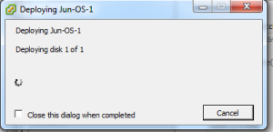


It may take a few minutes to import depending on the connection speed between your vSphere client and the ESXi server.
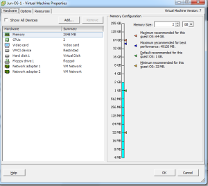
Once your machine uploaded you can then edit the settings.
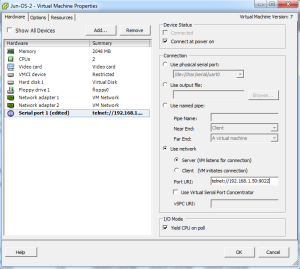
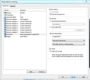
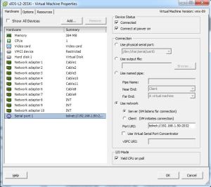
Two things we want to do here. First is that we want to alter the Network Adapter settings if needed and add a serial port so that we can use the virtual serial on the JunOS. This functionality (network based serial port) requires the Enterprise version of ESXi 5.1. I would recommend that you use the demo version which gives you 59 days unless you have to reinstall the demo
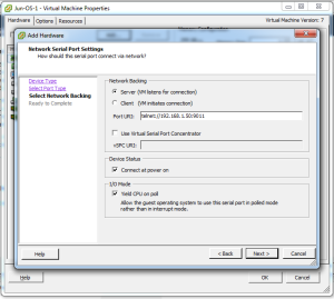
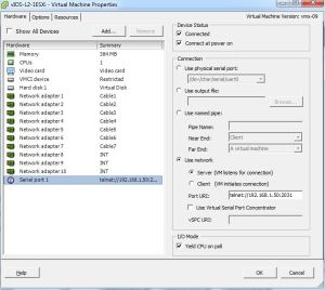
Add the serial port

Select “Connect via Network”

Now here is where you want to select “Server” and then enter the IP address of the ESXi server along with the TCP port you want to assign to this machine. Also check “Connect at power on”.

You will need to alter the default security settings for the ESXi server to allow TCP port 9011 or whatever port you selected to allow you to telnet to the JunOS serial port. To alter the security settings go to the ESXi’s configuration and then select “Security Profile”
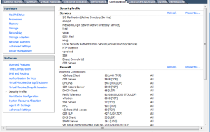

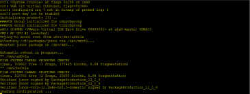
Here you will need to allow TCP port 9011 or if you are in a lab environment just select “VM serial port connected over network” which will open up all TCP high ports. Now telnet to the IP address of the ESXi machine and port number you entered for the serial port and you should see the router booting.
I will be deploying 8 devices so I will clone them.
To clone the machine go to the server configuration tab and then select the datastore where you installed the JunOS onto and then right click on it. From there select “Browse Datastore…”
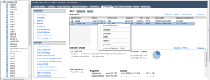
From here go under the directory for the JunOS-1 and copy the contents of the directory. From there click on the root of the datastore and then select the folder icon to add a new directory

Enter the directory name and then paste the contents into the new directory. After it has been pasted in, right click on the “Jun-OS-1.vmx” file and select “Add to Inventory”. Change the default name if you would like and select the “Resource Pool” and finally finish.

You should now see the second JunOS in your ESXi server’s inventory. From there we’ll edit the settings to change the TCP port number for the virtual serial port.
In my next post I will show you the Logical topology I am building and then I will show you how to configure it for both ipv4 and ipv6 from scratch.
Stay Tuned!!!!!!!!

In my previous post, I described how to connect 4 switches using ESXi.
As you are aware that Vios-L2 image only takes 384 Mb of Ram ( I have assigned 512 MB) we can build the same topology using Vmware Workstation.
However using Vmware Workstation there can be maximum of 19 Adapters only.
In Order to meet the above requirement, we need 13 cables.
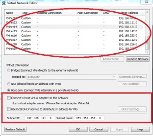
We need to go to Vmware Workstation — Edit — Virtual Network Editor.
The very important step here is that we need to add the network making sure we UNSELECT ( Connect a host virtual adapter to this network) and also UNSELECT ( Use Local DHCP Service) and hit apply.
You need to repeat the procedure for number of cables you need in your topology. I did this for 13 times.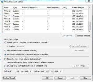
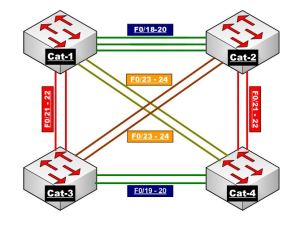
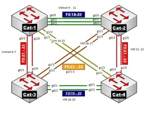
Below are the screen shots of my network adapter settings from the 4 switches :


Once you do the above settings and start the switches


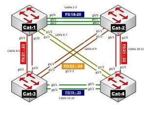
Below is the network Diagram for the same.
Hope this helps!!!!!
ate cable connection so that we can connect between the switches.
via Cable Connection’s on ESXI – Switching Topology using Cisco Vios.

Today, I will show you how to make cable connection between the switches using ESXi.
I could not find a proper document and hence I thought I will write this article so that this might help the other engineers using ESXi to build the virtual topologies more effectively.
I am using Vios-L2 image for this demo. Please do not ask me for this image and I am not going to SHARE this.
I am currenlty labbing from the Narbik Workbook. Please visit http://www.micronicstraining.com/ for their Workbook material.

I am going to show you how you can make the above topology virtually. The CCIE R n S version 5 is Vitual and hence I thought of implementing the same.
Looking at the above diagram, we see that we would need 4 x Virtual-Switches and 13 cables to interconnect them.
Let’s get Started
First we will create cable connection so that we can connect between the switches.
In order to do that, select ESXi host and then go to Configuration tab and then click Add Networking as shown below.


Once you click Add Networking, follow the below procedure as shown below.
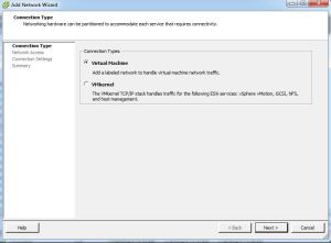
Select Virtual Machine and click NEXT
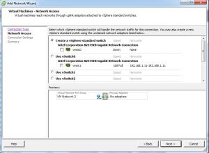
Make sure you un-select the VMNIC-0 as we just need a cable type connection so that we can connect two switches.
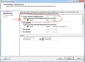
Once you un-select, hit Next.

Give a meaning Full Name to the Network Label and Select Vlan-ID (4095) and hit Next.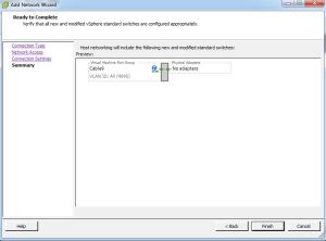
Now Click FINISH.
If you look under the configuration tab, you will see that the network connection is created and there is no adapters connected to it.
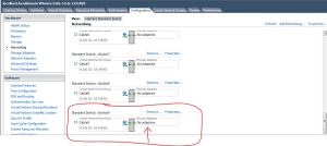
Using the above procedure, I have created 13 such connections.
I have connected 4 switches as per the below diagram.
If we examine the Network adapter settings for Sw-1, you should set it like below.
SW-2 Network Adapter settings :
SW-3 Network Adapter settings :

SW-4 Network Adapter settings :

Please note that the network adapters on these switches starts from G0/0 onwards.
Network Adapter 1 indicates its G0/0,
Network Adapter 2 indicates its G0/1,
Network Adapter 3 indicates its G0/2,
Network Adapter 4 indicates its G0/3,
Network Adapter 5 indicates its G1/0,
Network Adapter 6 indicates its G1/1,
Network Adapter 7 indicates its G1/2,
Network Adapter 8 indicates its G1/3,
Network Adapter 9 indicates its G2/0,
Network Adapter 10 indicates its G2/1.
As per my Understanding Cisco Vios images supports upto 10 Network Adapters. I might be wrong.
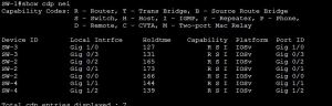
Let me start the switches and see what show CDP neighbor tells us 🙂
On SW-1 :
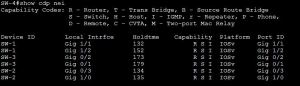
On SW-2

On SW-3

On SW-4

I will write another post in future with all the labs I do successfully on Vios-L2.
If you are using Vmware WorkStation then you can only make 19 connections and that is the maximum it supports.
I believe ESXi supports 120 connections which is more than enough for us to do the labs.
Ether channel is a technology that lets you bundle multiple physical links into a single logical link.
We’ll take a look at how it works and what the advantages of ether channel are.
I have two switches and two computers connected to the switches. The computers are connected with 1000 Mbit interfaces while the link between the switches is only 100 Mbit.
If one of the computers would send traffic that exceeds 100 Mbit of bandwidth we’ll have congestion and traffic will be dropped.
There are two solutions to this problem:
Replace the link in between the switches with something faster, 1000Mbit or maybe even 10 gigabit if you feel like.
In the below diagram you can see that I have added 3x 1000 MB links.

The problem with this setup is that we have a loop so spanning tree would block 2 out of 3 links.
This is where we will use Ether Channel to bundle multiple physical links and make them appear as a single Logical Link.
Below diagram show that 3 are bundled them using MLT ( Ether channel) resulting in one logical link with speed of 3000 MB.

There are 3 ways of configuring ether channel.
MLT (MultiLink Trunk) a proprietary bonding protocol to bond two or more physical links into a single virtual link between two switches.
DMLT (Distributed MultiLink Trunk) a proprietary bonding protocol to bond two or more physical links into a single virtual link across multiple cards or switches (in a stack configuration) between two switches.
An MLT/DMLT is Avaya’s proprietary equivalent to Cisco’s EtherChannel feature. An Avaya MLT or DMLT configuration can interoperate with Cisco’s EtherChannel configuration.
Deep Dive into MLT
MLT Types
Regular MLT
DMLT
MLT is a method for utilizing multiple physical connections between a given pair of switches, or between a switch and a server with multiple network interface cards (NICs), as a single logical link.
For instance, MLT can make four separate 100 MB links appear as a single 400 MB trunk. Should one of the links fail, the aggregate bandwidth is reduced to 300 MB, but the trunk itself remains up and continues to forward traffic as long as at least one physical connection is available.
Upper-layer protocols view the entire MLT bundle as a single logical interface. For example, if the Routing Information Protocol (RIP) learns a new route on one of the ports in the trunk, the next hop interface is the trunk itself. The actual port chosen for forwarding is transparent to Internet Protocol (IP) and RIP. This learning rule also applies to a media access control (MAC) address learned on a port in the trunk; the MAC address is identified in the forwarding database as being learned on the MLT.
When the time comes to forward a packet on a trunk, MLT chooses the physical port by performing a calculation on the addresses in the packet. Since many applications require that packets in a given session arrive in sequence, MLT consistently uses the same path for any given source/destination addresses pair. MLT does not keep track of sessions, however; it simply applies the same path selection algorithm to each packet, and the same addresses always yield the same path. For bridged traffic, the algorithm uses the MAC addresses. For routed IP or IPX traffic, the network layer addresses are used.
How Does MLT Work?
Forwarding Algorithm
The MLT forwarding algorithms are intended to provide load sharing while ensuring that packets do not get re-ordered and therefore do not arrive at the destination out of sequence. The algorithm ensures that packets with the same source and destination utilize the same path of the MLT.
Layer 2 Forwarding
When a data-frame is to be forwarded at Layer 2 (L2), the port to be used in the MLT group is determined by a combination of the source and destination MAC addresses of the data-frame. The six least significant bits of the source and destination MAC addresses are passed through an XOR calculation. The result of the XOR is divided by the number of active links in the MLT. The remainder of the division operation is used to determine the port number to be used to forward the Ethernet frame, where each port in the MLT is numbered in sequence starting at 0.
Layer 3 Forwarding
For Layer 3 (L3) forwarding, the source and destination IP/IPX addresses are used. All traffic for a session uses the same path in any given direction, assuring in-sequence delivery. However, multiple outbound sessions to the same server from different sources are distributed among the links. The algorithm for Layer 3 forwarding is the same as Layer 2 except the least significant bits of the Layer 3 source and destination address are used
Forwarding Algorithm
Frame Forwarding
L2 forwarding:
L3 forwarding:
Uses source and destination IP/IPX addresses
Address based path selection ensures in-sequence packet delivery
MLT provides the following benefits:
MLT Protocol
The assignment of switch ports to an MLT is manually configured on the two Switches at each end of an MLT. When the switch at either end of an MLT transmits a Spanning Tree BPDU on the MLT, it is required to transmit identical copies of the BPDU on each link that is assigned to the MLT.
The transmission of BPDUs on each link permits the switches to confirm that the MLT is properly connected between the two switches; e.g. all links of the MLT are connected between the same two switches. The Port Identifier parameter of Configuration BPDU’s is set to the Port Identifier of the highest priority port that is configured to belong to the MLT on the Designated Bridge (Port Identifier with the lowest numerical value), even if it is determined that the port is not operational.
The switches at each end of an MLT rely upon media dependent mechanisms, such as Auto-negotiation and Far End Fault detection and indication, to detect problems that might occur on one of the links of an MLT. When a link is found to be bad, the switches at each end of the MLT remove it from the MLT
Limitations
All ports in an MLT must be of the same:
MLT and Spanning Tree
Ports within a MLT behave as follows:
Configuration :
Configuration of an MLT is very very simple. Its just a 5 step procedure.
Note**: If you want the trunk links to be tagged then you need to configure the ports which are in the trunk to be tagged. This can be achieved via the below command.
Vlan ports 1,2 tagging tagAll
ON IST/SMLT ports we disable Spanning tree. I will write a separate article on IST/SMLT later.
Sample configuration and output from my Switch:
5k-Core1#show running-config module mlt
! Embedded ASCII Configuration Generator Script
! Model = Ethernet Routing Switch 5530-24TFD
! Software version = v6.3.3.040
!
! Displaying only parameters different to default
!================================================
enable
configure terminal
!
! *** MLT (Phase 1) ***
!
mlt 1 name “MLT-4-IST” enable member 23-24
!
! *** MLT (Phase 2) ***
!
mlt spanning-tree 1 stp 1 learning disable
5k-Core1#show mlt ?
Parameters:
LINE List of Trunk Groups
shutdown-ports-on-disable Display disabled trunk loop prevention status
spanning-tree Display multi-link trunk spanning-tree settings
utilization Display multi-link trunk utilization.
<cr>
5k-Core1#show mlt 1
Id Name Members Bpdu Mode Status Type
— —————- ———————- —— ————– ——- ——
1 MLT-4-IST 23-24 All Basic Enabled Trunk
5k-Core1#show mlt utilization 1
Trunk Traffic Type Port Last 5 Minutes Last 30 Minutes Last Hour
—– ———— —- ————– ————— ———
1 Rx and Tx 23 0.0% 0.0% 0.0%
1 Rx 23 0.0% 0.0% 0.0%
1 Tx 23 0.0% 0.0% 0.0%
1 Rx and Tx 24 0.0% 0.0% 0.0%
1 Rx 24 0.0% 0.0% 0.0%
1 Tx 24 0.0% 0.0% 0.0%
5k-Core1#show mlt spanning-tree 1
STP Group STP Learning
——— ————
1 Disabled
We will be doing the base configuration for INE Topology for CCIE RnS. If you haven’t purchase INE workbooks, go for it. Its really worth .
Below is the logical topology. 
I am using the Web IOU for configuring it. I have connected to all the devices, did bring up all the ports and configured hostnames only.
We will draw the diagram based on the outputs.
Note : This also helps a lot in real time customer’s network as most of the customer’s do not have the network diagram updated.
We will execute the command show cdp neighbors on all devices and will draw the diagram.
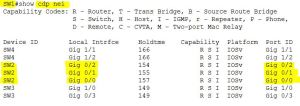
Rack1SW1#show cdp nei
Capability Codes: R – Router, T – Trans Bridge, B – Source Route Bridge
S – Switch, H – Host, I – IGMP, r – Repeater, P – Phone,
D – Remote, C – CVTA, M – Two-port Mac Relay
Device ID Local Intrfce Holdtme Capability Platform Port ID
Rack1SW4 Eth 4/0 137 R S Linux Uni Eth 2/0
Rack1SW4 Eth 4/1 137 R S Linux Uni Eth 2/1
Rack1SW4 Eth 4/2 137 R S Linux Uni Eth 2/2
Rack1SW2 Eth 2/0 137 R S Linux Uni Eth 2/0
Rack1SW2 Eth 2/1 137 R S Linux Uni Eth 2/1
Rack1SW2 Eth 2/2 137 R S Linux Uni Eth 2/2
Rack1SW3 Eth 3/0 137 R S Linux Uni Eth 2/0
Rack1SW3 Eth 3/1 137 R S Linux Uni Eth 2/1
Rack1SW3 Eth 3/2 137 R S Linux Uni Eth 2/2
Rack1R1 Eth 0/1 171 R Linux Uni Eth 0/0
Rack1R3 Eth 0/3 173 R Linux Uni Eth 0/0
Rack1R5 Eth 1/1 177 R Linux Uni Eth 0/0
The above output is execute on Switch 1. The Device ID shows the host-name of the neighboring device. Local Interface refers to the port on the device where the command was executed. In this example it is switch 1. Port ID refers to the neighboring device port.
Looking at the first 3 line, it says Switch1 is connected to Switch 4 via ethernet 4/0,e4/1,e4/2.
||SW-1||–e4/0————-e2/0–||Sw4||
||SW-1||–e4/1————-e2/1–||Sw4||
||SW-1||–e4/2————-e2/2–||Sw4||
Similarly,
||SW-1||–e2/0————-e2/0–||Sw2||
||SW-1||–e2/1————-e2/1–||Sw2||
||SW-1||–e2/2————-e2/2–||Sw2||
and
||SW-1||–e3/0————-e2/0–||Sw3||
||SW-1||–e3/1————-e2/1–||Sw3||
||SW-1||–e3/2————-e2/2–||Sw3||
So in Total we have 9 links from SW1 to other switches respectively. These 9 links would be configured as Trunk because we want the many vlans to be travel across these links.
We also have 3 links connecting to Routers R1,R3 and R5 via e0/1,e0/3 and e0/5 to their e0/0 ports.
||SW-1||–e0/1————-e0/0–||R1||
||SW-1||–e0/3————-e0/0–||R3||
||SW-1||–e0/5————-e0/0–||R5||
Similarly you can draw the complete the diagram following the above. I have pasted the outputs from SW2,SW3 and SW4 respectively.
Rack1SW2#show cdp nei
Capability Codes: R – Router, T – Trans Bridge, B – Source Route Bridge
S – Switch, H – Host, I – IGMP, r – Repeater, P – Phone,
D – Remote, C – CVTA, M – Two-port Mac Relay
Device ID Local Intrfce Holdtme Capability Platform Port ID
BB2 Eth 0/0 167 R Linux Uni Eth 0/0
Rack1SW4 Eth 4/0 165 R S Linux Uni Eth 3/0
Rack1SW4 Eth 4/1 165 R S Linux Uni Eth 3/1
Rack1SW4 Eth 4/2 165 R S Linux Uni Eth 3/2
Rack1SW3 Eth 3/2 165 R S Linux Uni Eth 3/2
Rack1SW3 Eth 3/1 165 R S Linux Uni Eth 3/1
Rack1SW3 Eth 3/0 165 R S Linux Uni Eth 3/0
Rack1SW1 Eth 2/1 165 R S Linux Uni Eth 2/1
Rack1SW1 Eth 2/2 165 R S Linux Uni Eth 2/2
Rack1SW1 Eth 2/0 165 R S Linux Uni Eth 2/0
Rack1R2 Eth 0/2 158 R Linux Uni Eth 0/0
Rack1R4 Eth 1/0 140 R Linux Uni Eth 0/0
Rack1R6 Eth 1/2 132 R Linux Uni Eth 0/0
Rack1SW3#show cdp nei
Capability Codes: R – Router, T – Trans Bridge, B – Source Route Bridge
S – Switch, H – Host, I – IGMP, r – Repeater, P – Phone,
D – Remote, C – CVTA, M – Two-port Mac Relay
Device ID Local Intrfce Holdtme Capability Platform Port ID
BB3 Eth 0/0 131 R Linux Uni Eth 0/0
Rack1SW4 Eth 4/0 150 R S Linux Uni Eth 4/0
Rack1SW4 Eth 4/1 150 R S Linux Uni Eth 4/1
Rack1SW4 Eth 4/2 150 R S Linux Uni Eth 4/2
Rack1SW2 Eth 3/2 150 R S Linux Uni Eth 3/2
Rack1SW2 Eth 3/1 150 R S Linux Uni Eth 3/1
Rack1SW2 Eth 3/0 150 R S Linux Uni Eth 3/0
Rack1SW1 Eth 2/2 150 R S Linux Uni Eth 3/2
Rack1SW1 Eth 2/1 150 R S Linux Uni Eth 3/1
Rack1SW1 Eth 2/0 150 R S Linux Uni Eth 3/0
Rack1R5 Eth 1/1 148 R Linux Uni Eth 0/1
Rack1SW4#show cdp nei
Capability Codes: R – Router, T – Trans Bridge, B – Source Route Bridge
S – Switch, H – Host, I – IGMP, r – Repeater, P – Phone,
D – Remote, C – CVTA, M – Two-port Mac Relay
Device ID Local Intrfce Holdtme Capability Platform Port ID
Rack1SW2 Eth 3/1 144 R S Linux Uni Eth 4/1
Rack1SW2 Eth 3/2 144 R S Linux Uni Eth 4/2
Rack1SW2 Eth 3/0 144 R S Linux Uni Eth 4/0
Rack1SW3 Eth 4/0 144 R S Linux Uni Eth 4/0
Rack1SW3 Eth 4/1 144 R S Linux Uni Eth 4/1
Rack1SW3 Eth 4/2 144 R S Linux Uni Eth 4/2
Rack1SW1 Eth 2/2 144 R S Linux Uni Eth 4/2
Rack1SW1 Eth 2/1 144 R S Linux Uni Eth 4/1
Rack1SW1 Eth 2/0 144 R S Linux Uni Eth 4/0
Rack1R4 Eth 1/0 176 R Linux Uni Eth 0/1
The resulting diagram would be referred as Physical Diagram. See Below :I made this diagram using GNS3.
Comparing it with the logical diagram we see that R1 E0/0 should be part of VLAN 146. So port E0/1 on SW1 should be an access port and member of VLAN 146. Traffic comming on port E0/1 on SW1 would be tagged as VLAN 146.
On SW1 we also have R5 0/0 connected to port E0/5. As per logical Diagram this should be in VLAN 5.
Port 0/3 on SW1 is a Routed Port. Hence we need to issue no switchport command under the interface and assign an IP address.
we see that R1 e0/0, R4 e0/1 and R6 e0/0 are part of VLAN 146.
So looking at the physical connections we just made, we see that on SW1 port e0/1 should be part of VLAN 146, SW4 E1/0 and SW2 e1/2 should be access ports belonging to VLAN 146.
There’s is a Catch!!! Watch closely…In the logical Diagram R6 E0/0 has 2 sub interface and these sub interfaces are in 2 different VLANS 🙂
That’s a Router ON a Staick Concept!!.
Its Simple :
On R6 :
int e0/0
no shutdown
exit
int e0/0.146 =====>Sub Interface number can be anything. We just give 146 here which is matching our Vlan number.
encapsulation dot1q 146
ip add 155.1.146.1 255.255.255.0
no shut
exit
int e0/0.67
encapsulation dot1q 67
ip add 155.1.67.6 255.255.255.0
no shut
exit
Sw1 E1/2 connects to R6 E0/0. Earlier we configured E1/2 as member of VLAN 146. Now we see that from the same interface we are receiving tagged packets i.e vlan 146 and Vlan 67. Hence this port should be TRUNK port.
On All Switches, we have ports E2/0-2, E3/0-2,E4/0-2 connecting to other switches. As a result we will be configuring these ports as Trunk Ports.
ON ALL Switches :
conf t
int range E2/0-2, E3/0-2,E4/0-2
Shutdown
exit
conf t
int range E2/0-2, E3/0-2,E4/0-2
Switchport trunk encap dot1q ————-> Using Dot1q encapsulation as ISL does not work on IOU.
switchport mode trunk ——> Hard Coding to be as Trunk ports.
exit
and on SW1
int e1/2
Switchport trunk encap dot1q
switchport mode trunk
exit
conf t
int range E2/0-2, E3/0-2,E4/0-2
No Shutdown
exit
Total VLANS used in this network topology : VLan 5,7,8,9,10,22,43,58,67,79,146
We will configure all these vlans on all the Switches.
On ALL SWITCHES:
en
conf t
Vlan 5,7,8,9,10,22,43,58,67,79,146
exit
Vlan Port configuration :SO
Some output Omitted
SW1#sh run int e1/1
interface Ethernet1/1
switchport access vlan 58
switchport mode access
duplex auto
spanning-tree portfast
end
Rack1SW1#sh run int e0/1
interface Ethernet0/1
switchport access vlan 146
switchport mode access
duplex auto
spanning-tree portfast
end
Rack1SW2#sh run int e0/0
!
interface Ethernet0/0
switchport access vlan 22
switchport mode access
duplex auto
spanning-tree portfast
end
Rack1SW2#sh run int e0/2
!
interface Ethernet0/2
switchport access vlan 22
switchport mode access
duplex auto
spanning-tree portfast
end
Rack1SW2#sh run int e1/0
!
interface Ethernet1/0
switchport access vlan 43
switchport mode access
duplex auto
spanning-tree portfast
end
Rack1SW3#sh run int e0/0
!
interface Ethernet0/0
switchport access vlan 43
switchport mode access
duplex auto
spanning-tree portfast
end
Rack1SW4#sh run int e1/0
!
interface Ethernet1/0
switchport access vlan 146
switchport mode access
duplex auto
spanning-tree portfast
end
So far we did
Now its time to assign IP address to the Devices and ping Directly connected interfaces to confirm if our Layer 1 and Layer 2 is UP and Running.
Its really important to have the complete understanding of the network Topology. INE has many labs on individual technology and all of them are based on this Network Diagram. They Use 6 Routers and 4 Switches.
You will notice that INE is using 155.x.y.z network in their topology.
X represents the RACK Number. In this case it is 1.
Y represents the numbering(Connection) between the devices. For ex: Link connects between R2 and R3 then Y would be 23.
It connection between R1,R4 and R6 then Y=146 etc.
Z represents the Router(Device) Number.
R1–1
R2–2
R3–3
R4–4
R5 — 5
R6 — 6
SW1 – 7
SW2 – 8
SW3 – 9
SW4 — 10
Now If you look at the above numbering you will find it very easy understanding the IP address used in the network. If connection between R6 and SW1 then the Ip subnet would be 155.1.67.z ( On R6 z=6 and on SW1 z=7).
So looking at the Logical Topology we need to configure the below IP address on the Devices. All the IP address subnet mask is /24.
On R1
Ethernet0/0—>155.1.146.1/24
Serial1/0—>155.1.0.1/24
Serial1/0.1–>155.1.0.1/24
Serial1/1—>155.1.13.1/24
Loopback0–>150.1.1.1/24
on R2
Ethernet0/0–>192.10.1.2/24
Serial1/0–>155.1.0.2/24
Serial1/0.1–>155.1.0.2/24
Serial1/1–>155.1.23.2/24
Loopback0–>150.1.2.2/24
R3
Ethernet0/0–>155.1.37.3
Serial1/0–> 155.1.0.3
Serial1/0.1–>155.1.0.3
Serial1/2–> 155.1.13.3
Serial1/3–> 155.1.23.3
Loopback0–> 150.1.3.3
R4
Ethernet0/0–>204.12.1.4
Ethernet0/1–>155.1.146.4
Serial1/0–> 155.1.0.4
Serial1/0.1–>155.1.0.4
Serial1/1–> 155.1.45.4
Loopback0–> 150.1.4.4
R5
Ethernet0/0–>155.1.58.5
Ethernet0/1–>155.1.5.5
Serial1/0–> 155.1.0.5
Serial1/1–> 155.1.45.5
Loopback0–> 150.1.5.5
R6
Ethernet0/0.67–>155.1.67.6
Ethernet0/0.146–>155.1.146.6
Serial1/0–> 54.1.1.6
Loopback0–> 150.1.6.6
SW1
Ethernet0/3–>155.1.37.7
Loopback0–> 150.1.7.7
Vlan7–> 155.1.7.7
Vlan67–> 155.1.67.7
Vlan79–> 155.1.79.7
SW2
Interface–> IP-Address
Ethernet4/0–>155.1.108.8
Loopback0–> 150.1.8.8
Vlan8–> 155.1.8.8
Vlan58–> 155.1.58.8
SW3
Loopback0–> 150.1.9.9
Vlan9–> 155.1.9.9
Vlan79–> 155.1.79.9
SW4
Ethernet3/0–>155.1.108.10
Loopback0–> 150.1.10.10
Vlan10–> 155.1.10.10
Verification :
Rack1SW1#show mac address-table
Mac Address Table
——————————————-
Vlan Mac Address Type Ports
—- ———– ——– —–
58 aabb.cc00.0500 DYNAMIC Et1/1
58 aabb.cc80.0800 DYNAMIC Et2/0
146 aabb.cc00.0100 DYNAMIC Et0/1
146 aabb.cc00.0410 DYNAMIC Et4/0
146 aabb.cc00.0600 DYNAMIC Et2/0
5 aabb.cc00.0510 DYNAMIC Et3/0
8 aabb.cc80.0800 DYNAMIC Et2/0
9 aabb.cc80.0900 DYNAMIC Et3/0
10 aabb.cc80.0a00 DYNAMIC Et4/0
22 aabb.cc00.0200 DYNAMIC Et2/0
22 aabb.cc00.0c00 DYNAMIC Et2/0
43 aabb.cc00.0400 DYNAMIC Et2/0
43 aabb.cc00.0d00 DYNAMIC Et3/0
67 aabb.cc00.0600 DYNAMIC Et2/0
79 aabb.cc80.0900 DYNAMIC Et3/0
Total Mac Addresses for this criterion: 15
Rack1SW2#show mac address-table
Mac Address Table
——————————————-
Vlan Mac Address Type Ports
—- ———– ——– —–
22 aabb.cc00.0200 DYNAMIC Et0/2
22 aabb.cc00.0c00 DYNAMIC Et0/0
43 aabb.cc00.0400 DYNAMIC Et1/0
43 aabb.cc00.0d00 DYNAMIC Et2/0
1 aabb.cc00.0600 DYNAMIC Et1/2
5 aabb.cc00.0510 DYNAMIC Et2/0
7 aabb.cc80.0700 DYNAMIC Et2/0
9 aabb.cc80.0900 DYNAMIC Et2/0
10 aabb.cc80.0a00 DYNAMIC Et2/0
58 aabb.cc00.0500 DYNAMIC Et2/0
67 aabb.cc00.0600 DYNAMIC Et1/2
67 aabb.cc80.0700 DYNAMIC Et2/0
79 aabb.cc80.0700 DYNAMIC Et2/0
79 aabb.cc80.0900 DYNAMIC Et2/0
146 aabb.cc00.0100 DYNAMIC Et2/0
146 aabb.cc00.0410 DYNAMIC Et2/0
146 aabb.cc00.0600 DYNAMIC Et1/2
Total Mac Addresses for this criterion: 17
Rack1SW2#
Rack1SW3#show mac address-table
Mac Address Table
——————————————-
Vlan Mac Address Type Ports
—- ———– ——– —–
5 aabb.cc00.0510 DYNAMIC Et1/1
43 aabb.cc00.0400 DYNAMIC Et2/0
43 aabb.cc00.0d00 DYNAMIC Et0/0
7 aabb.cc80.0700 DYNAMIC Et2/0
8 aabb.cc80.0800 DYNAMIC Et2/0
10 aabb.cc80.0a00 DYNAMIC Et2/0
22 aabb.cc00.0200 DYNAMIC Et2/0
22 aabb.cc00.0c00 DYNAMIC Et2/0
58 aabb.cc00.0500 DYNAMIC Et2/0
58 aabb.cc80.0800 DYNAMIC Et2/0
67 aabb.cc00.0600 DYNAMIC Et2/0
67 aabb.cc80.0700 DYNAMIC Et2/0
79 aabb.cc80.0700 DYNAMIC Et2/0
146 aabb.cc00.0100 DYNAMIC Et2/0
146 aabb.cc00.0410 DYNAMIC Et2/0
146 aabb.cc00.0600 DYNAMIC Et2/0
Total Mac Addresses for this criterion: 16
Rack1SW4#show mac address-table
Mac Address Table
——————————————-
Vlan Mac Address Type Ports
—- ———– ——– —–
146 aabb.cc00.0100 DYNAMIC Et2/0
146 aabb.cc00.0410 DYNAMIC Et1/0
146 aabb.cc00.0600 DYNAMIC Et2/0
5 aabb.cc00.0510 DYNAMIC Et2/0
7 aabb.cc80.0700 DYNAMIC Et2/0
8 aabb.cc80.0800 DYNAMIC Et2/0
9 aabb.cc80.0900 DYNAMIC Et2/0
22 aabb.cc00.0200 DYNAMIC Et2/0
22 aabb.cc00.0c00 DYNAMIC Et2/0
43 aabb.cc00.0400 DYNAMIC Et2/0
43 aabb.cc00.0d00 DYNAMIC Et2/0
58 aabb.cc00.0500 DYNAMIC Et2/0
58 aabb.cc80.0800 DYNAMIC Et2/0
67 aabb.cc00.0600 DYNAMIC Et2/0
67 aabb.cc80.0700 DYNAMIC Et2/0
79 aabb.cc80.0700 DYNAMIC Et2/0
79 aabb.cc80.0900 DYNAMIC Et2/0
Total Mac Addresses for this criterion: 17
Rack1R1#ping 255.255.255.255 repeat 2
Type escape sequence to abort.
Sending 2, 100-byte ICMP Echos to 255.255.255.255, timeout is 2 seconds:
Reply to request 0 from 155.1.146.6, 3 ms
Reply to request 0 from 155.1.0.5, 116 ms
Reply to request 0 from 155.1.13.3, 7 ms
Reply to request 0 from 155.1.146.4, 5 ms
Reply to request 1 from 155.1.146.4, 2 ms
Reply to request 1 from 155.1.0.5, 39 ms
Reply to request 1 from 155.1.13.3, 6 ms
Reply to request 1 from 155.1.146.6, 2 ms
Rack1R2#ping 255.255.255.255 re 2
Type escape sequence to abort.
Sending 2, 100-byte ICMP Echos to 255.255.255.255, timeout is 2 seconds:
Reply to request 0 from 192.10.1.254, 6 ms
Reply to request 0 from 155.1.0.5, 99 ms
Reply to request 0 from 155.1.23.3, 11 ms
Reply to request 1 from 192.10.1.254, 2 ms
Reply to request 1 from 155.1.0.5, 17 ms
Reply to request 1 from 155.1.23.3, 11 ms
Rack1R3#ping 255.255.255.255 re 2
Type escape sequence to abort.
Sending 2, 100-byte ICMP Echos to 255.255.255.255, timeout is 2 seconds:
Reply to request 0 from 155.1.37.7, 1 ms
Reply to request 0 from 155.1.0.5, 40 ms
Reply to request 0 from 155.1.23.2, 6 ms
Reply to request 0 from 155.1.13.1, 6 ms
Reply to request 1 from 155.1.37.7, 1 ms
Reply to request 1 from 155.1.0.5, 57 ms
Reply to request 1 from 155.1.23.2, 17 ms
Reply to request 1 from 155.1.13.1, 16 ms
Rack1R4#
Rack1R4#ping 255.255.255.255 re 2
Type escape sequence to abort.
Sending 2, 100-byte ICMP Echos to 255.255.255.255, timeout is 2 seconds:
Reply to request 0 from 204.12.1.254, 5 ms
Reply to request 0 from 155.1.0.5, 54 ms
Reply to request 0 from 155.1.146.6, 10 ms
Reply to request 0 from 155.1.146.1, 6 ms
Reply to request 0 from 155.1.45.5, 6 ms
Reply to request 1 from 155.1.146.1, 3 ms
Reply to request 1 from 155.1.0.5, 79 ms
Reply to request 1 from 155.1.45.5, 11 ms
Reply to request 1 from 204.12.1.254, 6 ms
Reply to request 1 from 155.1.146.6, 6 ms
Rack1R5#ping 255.255.255.255 re 2
Type escape sequence to abort.
Sending 2, 100-byte ICMP Echos to 255.255.255.255, timeout is 2 seconds:
Reply to request 0 from 155.1.58.8, 4 ms
Reply to request 0 from 155.1.0.1, 191 ms
Reply to request 0 from 155.1.0.4, 85 ms
Reply to request 0 from 155.1.45.4, 8 ms
Reply to request 1 from 155.1.58.8, 1 ms
Reply to request 1 from 155.1.0.1, 215 ms
Reply to request 1 from 155.1.0.4, 126 ms
Reply to request 1 from 155.1.45.4, 6 ms
Rack1R6#ping 255.255.255.255 re 2
Type escape sequence to abort.
Sending 2, 100-byte ICMP Echos to 255.255.255.255, timeout is 2 seconds:
Reply to request 0 from 155.1.67.7, 2 ms
Reply to request 0 from 54.1.2.254, 88 ms
Reply to request 0 from 54.1.1.254, 88 ms
Reply to request 0 from 54.1.3.254, 88 ms
Reply to request 0 from 155.1.146.4, 2 ms
Reply to request 0 from 155.1.146.1, 2 ms
Reply to request 1 from 155.1.67.7, 3 ms
Reply to request 1 from 54.1.2.254, 104 ms
Reply to request 1 from 54.1.1.254, 104 ms
Reply to request 1 from 54.1.3.254, 104 ms
Reply to request 1 from 155.1.146.4, 4 ms
Reply to request 1 from 155.1.146.1, 3 ms
Rack1R6#
Rack1SW1#ping 255.255.255.255 re 2
Type escape sequence to abort.
Sending 2, 100-byte ICMP Echos to 255.255.255.255, timeout is 2 seconds:
Reply to request 0 from 155.1.37.3, 5 ms
Reply to request 0 from 155.1.79.9, 6 ms
Reply to request 0 from 155.1.67.6, 5 ms
Reply to request 1 from 155.1.37.3, 6 ms
Reply to request 1 from 155.1.67.6, 6 ms
Reply to request 1 from 155.1.79.9, 6 ms
Rack1SW2#ping 255.255.255.255 re 2
Type escape sequence to abort.
Sending 2, 100-byte ICMP Echos to 255.255.255.255, timeout is 2 seconds:
Reply to request 0 from 155.1.108.10, 8 ms
Reply to request 0 from 155.1.58.5, 8 ms
Reply to request 1 from 155.1.108.10, 2 ms
Reply to request 1 from 155.1.58.5, 2 ms
Rack1SW3#ping 255.255.255.255 re 2
Type escape sequence to abort.
Sending 2, 100-byte ICMP Echos to 255.255.255.255, timeout is 2 seconds:
Reply to request 0 from 155.1.79.7, 3 ms
Reply to request 1 from 155.1.79.7, 20 ms
Rack1SW4#ping 255.255.255.255 re 2
Type escape sequence to abort.
Sending 2, 100-byte ICMP Echos to 255.255.255.255, timeout is 2 seconds:
Reply to request 0 from 155.1.108.8, 1 ms
Reply to request 1 from 155.1.108.8, 2 ms
Hope this Helps 🙂
